Component Diagram
A component diagram depicts how modules are wired together to form larger features or software systems and how they are structured.
Diagram Model
Name |
Graphical Representation |
Description |
|---|---|---|
Component / Module |
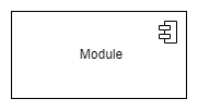
|
Replaceable, modular piece of a system. The interactions with other modules are described by its provided and required interfaces. |
Interfaces |
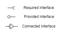
|
|
Port |

|
|
Interface Dependency and Assembly Relationship |
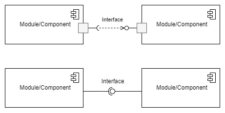
|
|
Manifest Relationship |
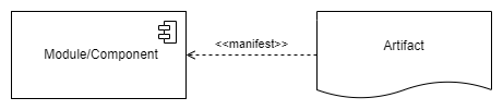
|
Artifacts that represent the physical realization of a component, have a manifest relationship towards the component. |
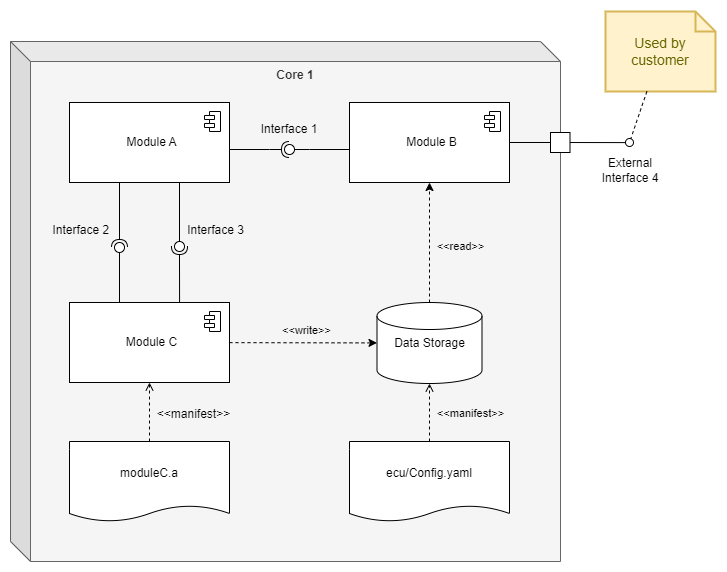
Example