Deployment Diagram
A deployment diagram models the physical deployment of artifacts on components in a system.
Diagram Model
Name |
Graphical Representation |
Description |
|---|---|---|
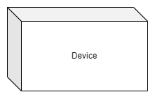
Device |
|
A device is a deployment target which represents a computational resource, e.g. hardware component with processing capabilities upon which artifacts or software components may be deployed for execution. A device can be connected to other devices and communicate with other devices. Hierarchical devices can be modeled using composition or by defining an internal structure. Examples are: µCs, µPs, cores, switches, crystals, etc. |
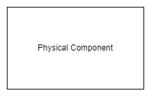
Physical Component |
|
A physical component represents physical parts, which are used by the device to provide the processing capabilities, e.g. RAM, ROM, flash, cache, etc. Physical components do not provide processing capabilities. |
Component / Module |

|
Replaceable, modular piece of a system, see also Component Diagram. |
Communication Path |
|
A communication path is an association between two deployment targets, through which they are able to exchange signals and messages. |
Example
