Use Case Diagram
A use case diagram is a graphical depiction of a user’s possible interactions with a system.
Note, that use-cases are not intended to have any sequencing between them. If you want to sequence behaviors, you should consider e.g. activity or sequence diagrams.
Diagram Model
Name |
Graphical Representation |
Description |
|---|---|---|
Actor |
|
Models a role that an external actor or external system can take during an interaction with the system. Actors are always outside the system boundary. |
Use Case |
|
Defines a fixed set of actions that are provided by the system. Use cases must have a visible benefit for one or more actors. |
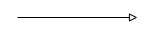
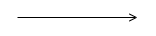
Association |
|
An association models a relationship between actors and use cases. |
Include |
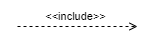
|
The include relationship supports reuse of use cases. Each time, the including use case is called, the included use case is also executed (similar to the call of a subfunction). It is important to avoid inclusion cycles. |
Extend |
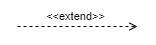
|
An existing use case can be extended. Please note the direction of the arrows. It’s not an “extended by” logic! |
Condition |
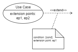
|
An extend relationship can be annotated with a condition. If that condition applies, the corresponding use case is taken into account.
To model the annotation, use a note shape in white/grey/black color (not the regular note color as described in Annotations). |
Specialization |
|
Generalization defines a relationship between a general and a more specific element. Use cases and actors can be generalized. |
Realize |
|
Used to show which classes, components, etc. realize the use case. Usually, this relationship is not modelled in a use case diagram. |
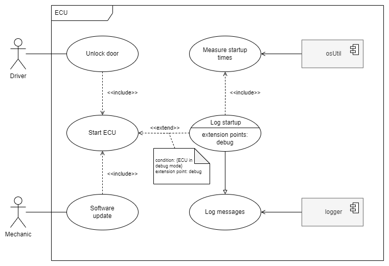
Example