Testing Guide
ReferenceApp Test Guide
1. Hardware Set Up:
a. Hardware Required
common
S32K148 Evaluation Board (EVB)
USB micro-B
12 V power supply
Testing CAN:
PEAK CAN USB Dongle and cable
Testing ADC:
Variable Power Supply – 0 to 5v
Testing PWM:
Digital Oscilloscope
b. Physical Connection
Common
Connect USB micro-B cable between Evaluation Board and Laptop
Connect 12-volt power supply to EVB.
Testing CAN:
Connect EVB CAN Header Pin to the PEAK CAN Device as below.
Header Pin in EVB
D Port in PEAK CAN
CAN L
Pin 2
CAN H
Pin 7
Connect PEAK CAN USB cable to Laptop.
Testing ADC:
Connect Variable Power Supply to ADC Input.
Variable Power
TP in EVB
+ve Connector
TS9
Gnd Connector
GND
Testing PWM:
Connect DSO probe to PWM output pin
LED
Blue
PTE23
J5-5
Channel - 3
Green
PTE22
J5-3
Channel - 2
DSO
TP in EVB
+ve Connector
Any channel
Gnd Connector
GND
Testing IO:
- Connect LED to IO pin
LED
Red
PTE21
J5-1
Channel - 1
2. Flash the Software:
Launch S32 Design Studio (We tested on S32 Design Studio for ARM Version 2.2).

b. Select Debug Configuration

c. Under Debugger tab, select the proper Interface and device: S32k148

d. Under Main tab, browse and select the elf file to flash on target
For more information, refer to this link Flash, debug and test serial console on Windows
3. Configure Tera Term for Serial Debug
Start Tera Term.
Select the radio button labeled “Serial.”
Choose the COM port from the drop-down menu for the device you want to connect to and click “OK.”

Click on “Setup” in the menu bar and select “Serial Port.”
In the Serial Port Setup menu, configure the protocols as follows:
Tera Term should now be properly configured for serial communication with EVB.

4. Testing Sequence: ADC
Open Tera Term console.
Give command “adc get 0” in Tera Term to read ADC Channel 0 (which is connected to Variable Power Supply. Adc Raw value and mV Scaled value will print.
Vary the voltage using Variable power supply (Range: 0 – 5v) and ensure the values are matching.
adc get 0
Adc Channel 0: AiEval_Poti_ADC -> : 1064 (raw) 1299 mv (scaled)
ok
412993: RefApp: CONSOLE: INFO: Received console command "adc get 0"
413000: RefApp: CONSOLE: INFO: console command Succeeded
5. Testing Sequence: PWM
- Duty Cycle of PWM can be changed using 2 ways:
Through potentiometer
Through console command
Changing PWM Duty cycle through potentiometer: By changing the position of potentiometer, the duty cycle of PWM can be changed.
Changing PWM Duty cycle through console command:
i.Stop DemoSystem lifecycle using command lc level 7
lc level 7
 ok
10133: RefApp: CONSOLE: INFO: Received console command "lc level 7"
10134: RefApp: CONSOLE: INFO: console command Succeeded
10135: RefApp: LIFECYCLE: INFO: Shutdown level 8
10135: RefApp: LIFECYCLE: INFO: Shutdown demo
10136: RefApp: LIFECYCLE: DEBUG: Shutdown demo done
10136: RefApp: LIFECYCLE: DEBUG: Shutdown level 8 done
ii.Through tera term change duty cycle to 20 % using command
help
 ok
6937: RefApp: CONSOLE: INFO: Received console command "help"
7036: RefApp: CONSOLE: INFO: console command Succeeded
pwm set 2 2000

PWM channel 2 (eval_led_green_pwm) set to 0x1388 % On

19355: RefApp: CONSOLE: INFO: Received console command "pwm set 2 2000"
19360: RefApp: CONSOLE: INFO: console command Succeeded
pwm set channel # value from 0-10000 pwm set 2 2000
For 50% duty cycle use command: pwm set 2 5000
This command can be used to change the duty cycle for all available channels (currently - 3). Duty cycle can be changed from 0-100 % using values from 0 – 10000.
The following are the screenshots saved from DSO for 20, 50 and 80% duty cycle.
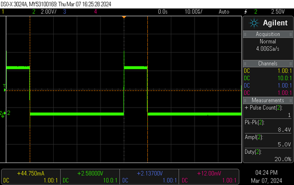
20% duty cycle
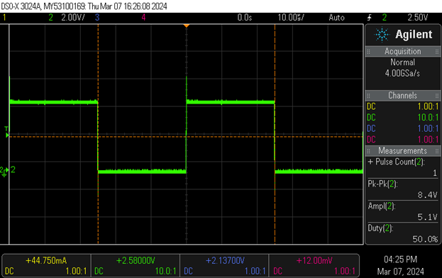
50% duty cycle
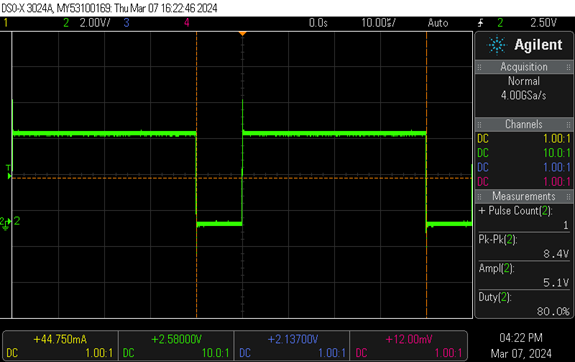
80% duty cycle
Testing Sequence: CAN
Sending CAN messages using vcan.
Send command
On the terminal stop DemoSystem lifecycle using command lc level 7
CAN frames sent can be seen as shown below.
The CAN send command allows you to send a frame with a specified ID and data bytes. Upon successful execution, the console will return an ok message, confirming that the frame has been sent:
can send 1 2 3 4 5 6 7 8
ok
RefApp: CONSOLE: INFO: Received console command "can send 1 2 3 4 5 6 7 8"
RefApp: CONSOLE: INFO: Console command succeeded
Info command
CAN info command provides information about the CAN bus.
This command retrieves and displays the current CAN bus information.
Upon successful execution, the console will return the number of CAN buses:
can info
CanBus : 2
ok
RefApp: CONSOLE: INFO: Received console command "can info"
RefApp: CONSOLE: INFO: Console command succeeded
Sending CAN messages using EVB and PEAK CAN
Open Tera Term console.
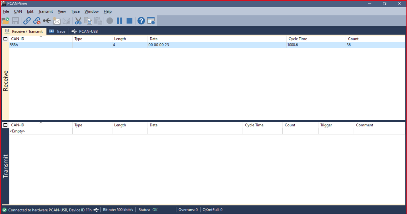
CAN frames sent can be seen as below.
71022: RefApp: DEMO: DEBUG: Sending frame 1
72022: RefApp: DEMO: DEBUG: Sending frame 2
73022: RefApp: DEMO: DEBUG: Sending frame 3
74022: RefApp: DEMO: DEBUG: Sending frame 4
75022: RefApp: DEMO: DEBUG: Sending frame 5
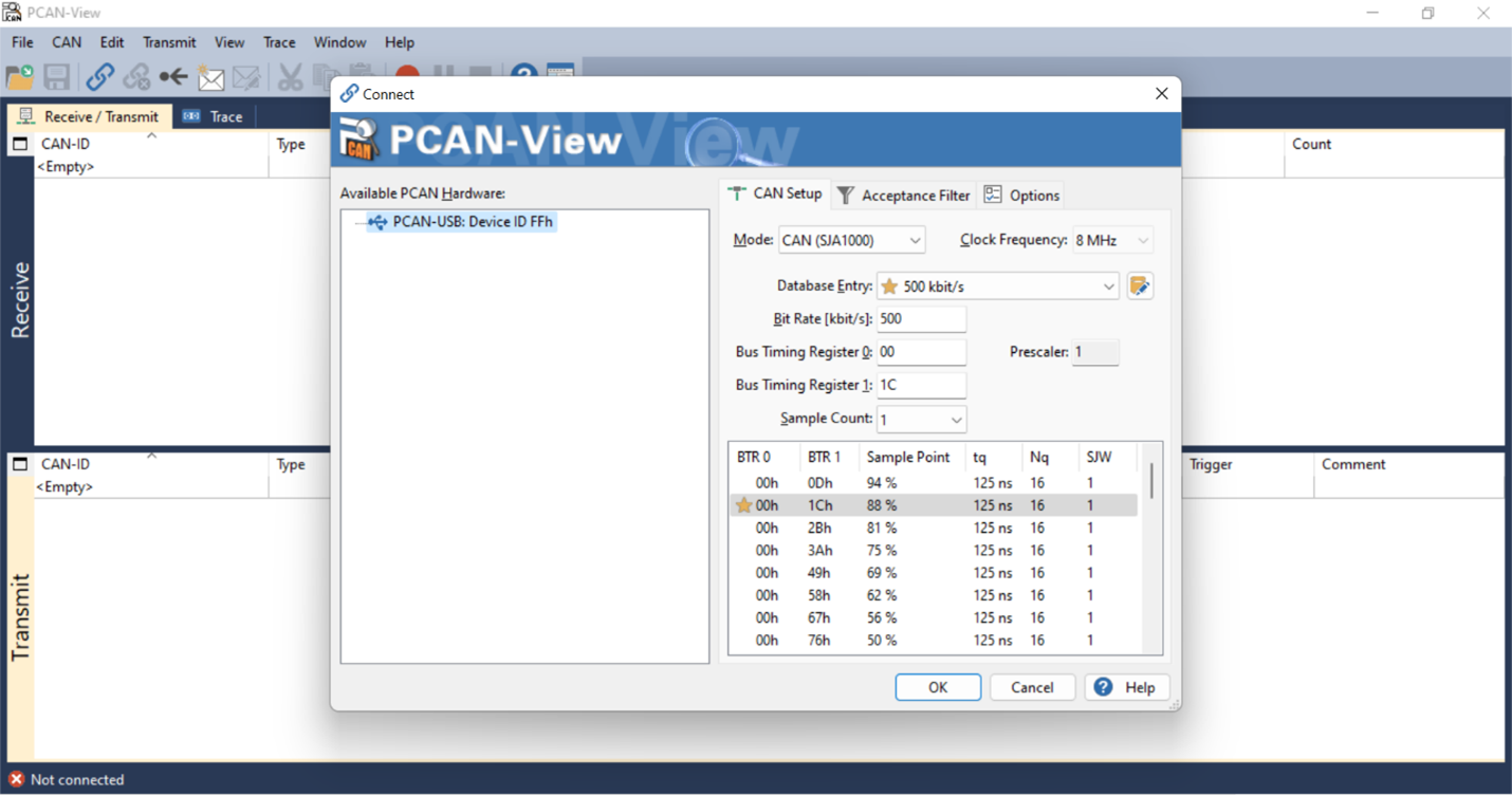
Open PCAN viewer. Configure Bitrate and other parameters as shown below
d.CAN frames sent can also be seen in the PCAN viewer as shown
6. Testing Sequence: IO
- IO can be verified using 2 ways:
Through pressing the switch button sw3 on EVB
Through console command
By pressing the switch button sw3 on EVB, the RED LED can be turned on. Here sw3 acts as input and RED LED as output.
Changing the IO through console command:
out set 1 1
help
 ok
out set 1 1
 1 : EVAL_LED_RED -> ok
 ok

330162: RefApp: CONSOLE: INFO: Received console command "out set 1 1"
330166: RefApp: CONSOLE: INFO: console command Succeeded
